

Building expansion joints are deliberate gaps that divide a structure, wall or floor into separate parts so each part can expand, shrink and move without cracking. They are needed because every building material changes size with temperature and moisture, and long, restrained elements would otherwise crack. This guide, for architects, students and self-builders, explains what building expansion joints do, where they are required, how far apart they go, with sourced movement data, a worked calculation and a typical brick veneer detail.
All buildings are restrained to some degree, by their foundations, cores and connections. In order to absorb the thermal expansion and contraction of construction materials, expansion joints are used. Materials expand in hot weather and contract when it is cold, and the stresses this creates grow with the size of the temperature change and the length of the restrained element. Large temperature ranges must therefore be accounted for at the design stage.
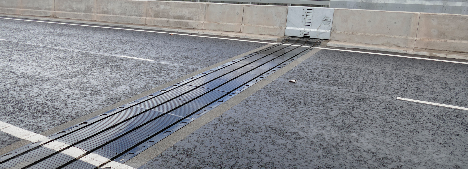
horizontal expansion joints
What are expansion joints used for?
The main job of an expansion joint is to accommodate movement. That movement can come from temperature changes, moisture (clay bricks grow slightly over their life, while concrete and concrete blocks shrink), settlement of the ground, creep and, in seismic zones, earthquakes. Joints at the boundaries between parts of a building with different foundations, heights or structural systems also stop movement in one part from damaging another.
A joint is usually closed with a cover, filler or sealant, so it must also keep out water and air, carry foot or vehicle traffic where it crosses a floor, and in many locations maintain the fire resistance of the wall or floor it passes through. Fire-rated joint systems are tested to their own standards, for example UL 2079 in the United States and EN 1366-4 in Europe.
The terms vary. “Expansion joint” and “movement joint” are often used interchangeably; a “control joint” (or contraction joint) is a weakened line that lets concrete or concrete masonry crack neatly as it shrinks, while a true expansion joint is an open gap through the element. A joint can do both jobs: by separating a building into segments it relieves expansion, and it also gives contraction a place to happen.
Expansion joints are used in many structures besides buildings, including bridges, pavements, railways and piping. In buildings they can run through floors, walls, roofs and facades, and can be placed floor-to-floor, floor-to-wall, wall-to-wall, ceiling-to-wall, roof-to-roof or roof-to-wall.
How much do building materials move?
Thermal movement is calculated as ΔL = α × L × ΔT, where α is the material’s coefficient of thermal expansion, L the length and ΔT the temperature change. The table gives design values from the Eurocodes and the Brick Industry Association (BIA), with the movement each would show over 10 m for a 40 K (72 °F) temperature change.
| Material | Coefficient of thermal expansion | Movement over 10 m for 40 K | Other movement | Source |
|---|---|---|---|---|
| Normal concrete | 10 x 10^-6 per K | 4.0 mm | Drying shrinkage and creep (shortening) | EN 1992-1-1 (Eurocode 2), 3.1.3 |
| Structural steel | 12 x 10^-6 per K | 4.8 mm | None significant | EN 1993-1-1 (Eurocode 3), 3.2.6 |
| Aluminium alloys | 23 x 10^-6 per K | 9.2 mm | None significant | EN 1999-1-1 (Eurocode 9) |
| Clay brickwork (total, all causes) | – | About 9 mm (0.0009 x length, all causes) | Irreversible moisture expansion over its life | BIA Technical Note 18A (2019) |
Source: Eurocodes (CEN) and Brick Industry Association TN 18A (May 2019); movements calculated by Arch2O (as of 1 November 2026).
Two points stand out. Aluminium moves more than twice as much as concrete or steel, which is why curtain walls and facade materials such as aluminium cladding need movement joints at every panel or mullion. And clay brickwork moves in one direction over its life, growing as it absorbs moisture, so brick joints must allow for permanent expansion, not just a seasonal cycle.
Worked example: sizing movement in three elements
The figures below are illustrative; a structural engineer sets the actual design temperature range and joint widths for a project.
- Concrete frame, 60 m long, design temperature change 30 K: 10 × 10−6 × 60,000 mm × 30 = 18 mm of movement, before shrinkage and creep are added.
- Aluminium curtain-wall mullion, 4 m long, surface temperature range 70 K: 23 × 10−6 × 4,000 mm × 70 = 6.4 mm, taken up at the joint between mullions at each floor.
- Clay brick veneer: BIA Technical Note 18A (May 2019) estimates the total expansion of most unrestrained brickwork as its length multiplied by 0.0009. For a 7.6 m (25 ft) panel that is about 6.8 mm. The note gives joint spacing as S = w × e ÷ 0.09, where w is the joint width and e the percentage compressibility of the joint filler. With a 12.7 mm (½ in) joint and a filler that compresses by 50%, S = 12.7 × 50 ÷ 0.09 ≈ 7,060 mm, or about 7 m (23 ft).
This is why recommended spacings exist: they are the distance at which a joint of normal width can still absorb the movement. Wider joints or more compressible fillers allow wider spacing, within limits.
Where are expansion joints required?
Expansion joints are needed wherever movement would otherwise be restrained or concentrated. Typical locations are:
- along long walls, floors and roofs, at spacings set by the material (see the table below);
- at changes in building height, shape (for example the corner of an L- or T-shaped plan), foundation type or structural system;
- where new work meets existing buildings;
- at corners, offsets, setbacks and changes of wall backing in masonry veneers, and below each shelf angle that supports brickwork;
- between the separate structural blocks of a building in a seismic zone, where joints must be wide enough to stop the blocks hitting each other, a key concern in disaster-proof homes.

Connection between the Solaria Stage and Nishitetsu Fukuoka Station buildings, Fukuoka, where an expansion joint separates the two structures. Photo: Hirho, CC BY-SA 4.0, via Wikimedia Commons. Hirho, source, CC BY-SA 4.0
The photograph shows the connection between two separate buildings at Nishitetsu Fukuoka Station in Japan, where an expansion joint lets each structure move independently, a common arrangement where buildings of different heights or ages are linked.
| Wall type | Typical maximum spacing | Jurisdiction / source | Notes |
|---|---|---|---|
| Clay brick veneer, no openings | 7.6 m (25 ft) | USA – BIA TN 18A (2019) | Also at corners, offsets, height changes |
| Clay brick veneer, multiple openings | 6.1 m (20 ft) | USA – BIA TN 18A (2019) | Place joints symmetrically about openings |
| Clay brickwork | 12 m | UK – warranty guidance (Premier Guarantee); PD 6697:2019 per secondary sources | Joint widths up to about 16 mm reported for 12 m centres |
| Calcium silicate brickwork | 7.5 to 9 m | UK – warranty guidance (Premier Guarantee) | |
| Concrete brickwork / blockwork | 6 m (warranty); 7.5 to 9 m (PD 6697, per manufacturer bulletin) | UK – Premier Guarantee; Marshalls | Depends on the product's shrinkage |
Source: BIA TN 18A (2019); Premier Guarantee movement joint guidance; Marshalls technical bulletin (as of 1 November 2026).
Joint spacing for structural frames is a matter for the structural engineer, who considers the building’s length, the design temperature range, whether it is heated, how its columns are fixed and how its floors are restrained. A long-standing US reference is the National Research Council’s Expansion Joints in Buildings, Technical Report No. 65 (1974).
What a good joint must do
Beyond allowing movement, a joint and its cover are expected to:
- carry the loads that cross them, from foot traffic to vehicle wheels;
- stay watertight at the joint and along its edges;
- be safe to walk on, including in narrow heels;
- resist chemicals where they are present;
- limit vibration where delicate goods are moved;
- look neat and fit the surrounding finishes.
Typical detail: vertical expansion joint in brick veneer
A drawing of this detail is to be produced in-house for Arch2O. The assembly below follows BIA Technical Note 18A (2019), a US source; check local guidance and manufacturers’ instructions for other countries.
- Open joint: a continuous, unobstructed gap through the full thickness of the brick skin, from foundation or shelf angle to the top of the wall, including any parapet. No mortar, bricks or rigid ties may bridge it.
- Filler: a highly compressible material, or nothing, inside the joint. Rigid fillers stop the joint from closing.
- Backer rod: a circular foam rod behind the sealant to control its depth and give it a surface to be tooled against.
- Sealant: an elastomeric sealant to ASTM C920, Grade NS, Use M, with Class 50 movement capability recommended (Class 25 as an alternative), with primer where the manufacturer requires it.
- Ties and backing: wall ties on each side of the joint, and flashing and the cavity behind kept continuous.
Horizontal joints follow the same principle: BIA recommends a space or compressible material at least 6.4 mm (¼ in) deep immediately below each shelf angle, so the expanding brickwork does not bear on the steel above.
Applications of expansion joints in buildings
1. Shopping malls
Large floor plates in malls need floor joint covers that carry heavy pedestrian and trolley traffic without becoming trip hazards. Covers are made in aluminium, stainless steel and other materials, with inserts that can be matched to the floor finish so the joint is barely noticed.
2. Multi-storey parking areas and parking ramps
Car park joints must be watertight and resist de-icing salt, fuel and oil, as well as constant wheel loads and exposure to the weather. Leaking joints are a common route for chloride-laden water to reach the reinforcement in the slabs below.
3. Hospitals, laboratories and food factories
Hygiene is the main concern in these buildings, so joint covers should have smooth, sealed surfaces without gaps where dirt or bacteria can collect, and be easy to clean thoroughly.
4. Chemical plants
Joint materials must be selected for chemical resistance to the specific substances handled. Check the sealant or cover manufacturer’s chemical resistance data against the process chemicals before specifying.
Maintenance and common failures
- Sealant failure: sealants harden, crack and lose adhesion with age and ultraviolet exposure. Inspect regularly and replace failed lengths with the same class of sealant.
- Bridged joints: mortar droppings, rigid fillers or later repairs that fill the gap stop the joint working and move the cracking elsewhere.
- Missing joints: long brick walls without joints often show vertical cracks near corners or diagonal cracks around openings.
- Damaged covers: loose or damaged floor covers are trip hazards and let water into the structure below.
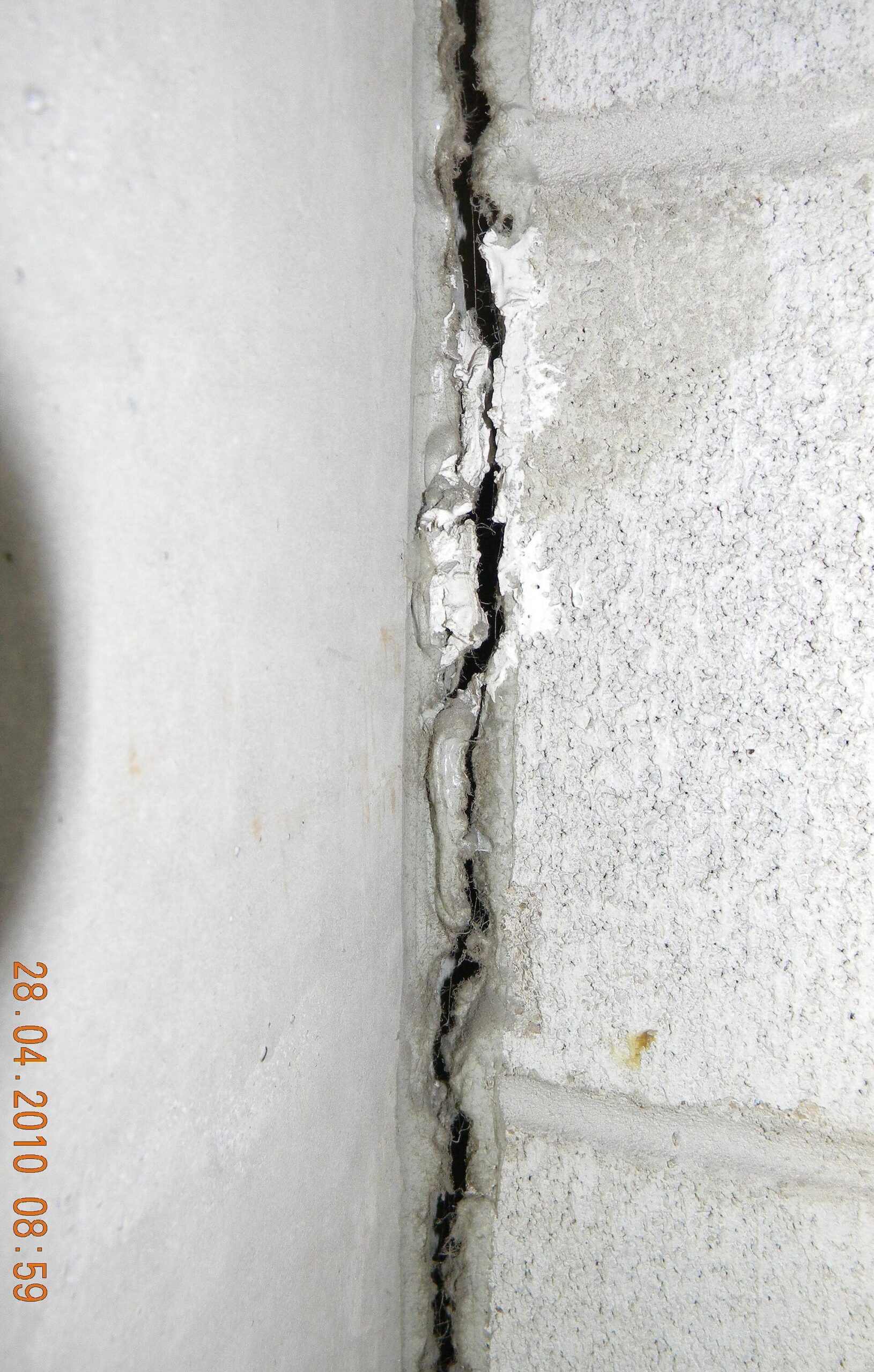
A failed building joint with torn sealant. Photo: Achim Hering, CC BY 3.0, via Wikimedia Commons. Achim Hering, source, CC BY 3.0
The close-up shows a failed joint: the sealant has torn away from the wall, opening a path for water. Torn or debonded sealant like this should be cut out and replaced, after checking why it failed (wrong sealant class, a joint too narrow for the movement, or poor surface preparation).
Summary and next step
Building expansion joints are planned gaps, not defects. Calculate the movement with ΔL = α × L × ΔT plus any moisture movement, place joints where the movement concentrates, and detail them so nothing bridges the gap. For a real project, agree the joint layout with the structural engineer early, then check spacings against the guidance for your country and material.
Sources and further reading
- Brick Industry Association, Technical Note 18A: Accommodating Expansion of Brickwork (May 2019).
- EN 1992-1-1 (Eurocode 2), EN 1993-1-1 (Eurocode 3) and EN 1999-1-1 (Eurocode 9): coefficients of thermal expansion for concrete, steel and aluminium.
- Premier Guarantee: Guidance on the use of movement joints (UK warranty guidance on masonry joint spacing).

Emily Reyes is a Brooklyn-based architecture writer and Article Curator at Arch2O, known for her sharp eye for experimental design and critical theory. A graduate of the Southern California Institute of Architecture (SCI-Arc), Emily’s early work explored speculative urbanism and the boundaries between digital form and physical space. After a few years in Los Angeles working with boutique studios on concept-driven installations, she pivoted toward editorial work, drawn by the need to contextualize and critique the fast-evolving architectural discourse. At Arch2O, she curates articles that dissect emerging technologies, post-anthropocentric design, and contemporary spatial politics. Emily also lectures occasionally and contributes essays to independent design journals across North America.