

Axonometric vs isometric is not a choice between two different things: isometric is one type of axonometric drawing. “Axonometric” is the family name for parallel projections that show a building in three dimensions with all parallel lines kept parallel, so the drawing can be measured. Isometric is the member of that family in which the three main axes are drawn at equal angles of 120° to each other, usually 30° from the horizontal. Dimetric and trimetric are other axonometric projections. The plan-oblique view that architects often call “axo” is a separate oblique construction. This guide explains each type, when to use it, how to draw an exploded axonometric step by step, and how to set up parallel views in common design software.
It is written for architecture students, who meet these terms in their first drawing classes and are often told different things by different tutors.
Axonometric vs isometric: the short answer
- Orthographic axonometric = a parallel projection onto a picture plane oblique to the principal object axes; isometric, dimetric and trimetric are its main cases.
- Isometric = an axonometric in which the three axes are equally inclined (120° apart), so all three are equally foreshortened.
- So every isometric is an axonometric, but not every axonometric is an isometric.
The projection family
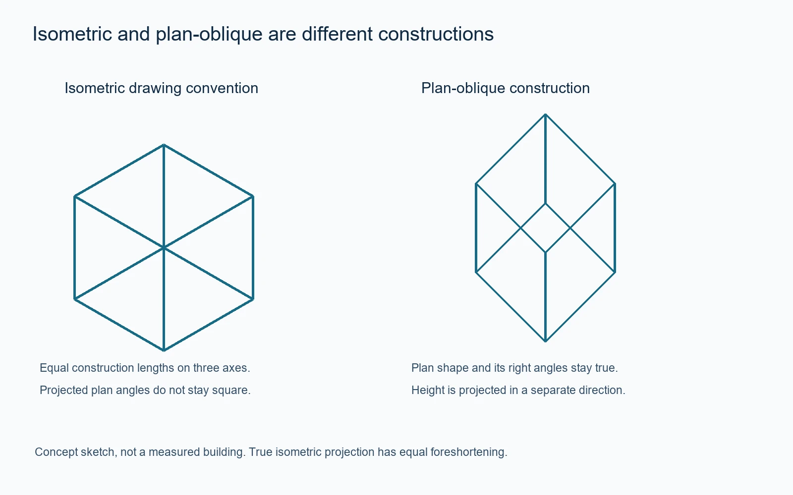
ISO 5456-3 identifies axonometric representations within technical projection methods. The distinction below separates orthographic axonometric views from plan-oblique construction.
The table compares the parallel projections used in architecture. All of them keep parallel lines parallel, which is why they can be measured along their axes, unlike a perspective.
| Projection | Axes | Scales | Plan shape | Best for |
|---|---|---|---|---|
| Isometric | Three axes 120° apart (30° from horizontal) | Equal on all three | Distorted (rhombus) | Details, objects, systems |
| Dimetric | Two principal axes have equal foreshortening | Two equal, one different | Distorted | Natural-looking views from a 3D model |
| Trimetric | All three axes differently inclined | All different | Distorted | Views from a chosen viewpoint |
| Plan oblique (45/45, 30/60) | Plan rotated, verticals upright | Plan true; verticals true or reduced | True shape | Interiors, roof-off views, urban blocks |
| Perspective (for comparison) | Lines converge to vanishing points | Not measurable | Distorted | Experience at eye level |
Source: Onshape help (isometric, dimetric, trimetric); standard drawing practice (as of 21 October 2026).
Isometric (30° / 30°)
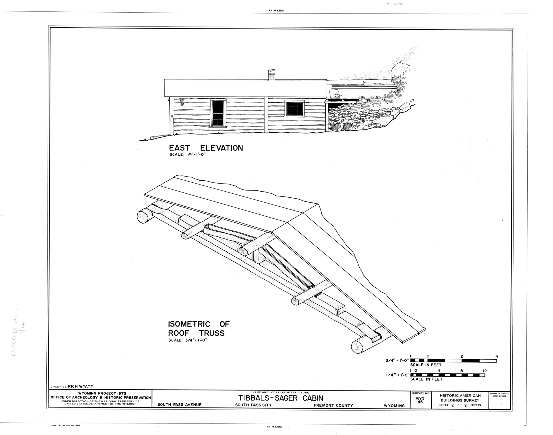
In an isometric drawing, the vertical axis stays vertical and the two horizontal axes are drawn at 30° to the horizontal, so all three axes are equally inclined with 120° between them. Because all three are equally foreshortened, an isometric drawing can be drawn at the same scale along all three axes, which makes it simple to construct with a 30/60 set square. Its weakness for architecture is that the plan is distorted: rectangles become rhombuses and circles become ellipses.
Dimetric and trimetric
In a dimetric projection, two axes share the same scale and the third is foreshortened differently; in a trimetric projection, all three are different. These are closer to how a building looks from a particular viewpoint and are common in computer views, but they are harder to construct by hand because each axis needs its own scale.
Plan oblique (45°/45° and 30°/60°)
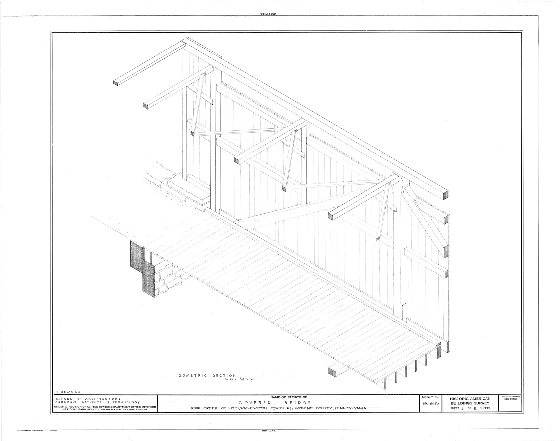
This is what many architecture schools mean by “an axo”. The plan is drawn at its true shape and scale, rotated (usually at 45°/45° or 30°/60°), and the verticals are projected straight up at true height (sometimes reduced). Because the plan is undistorted, you can draw it directly from the floor plan, and right angles stay right angles. That makes plan obliques ideal for showing interiors, roof-off views and the relationship between plan and volume. Strictly speaking it is an oblique projection rather than a true axonometric, but in architectural usage the two names are used interchangeably.
Where perspective differs
A perspective drawing uses vanishing points, so parallel lines converge and distant objects look smaller, as the eye sees them. It is the most realistic view, but you cannot measure it directly. Axonometric drawings sacrifice realism for measurability and clarity, which is why they are preferred for explaining how a building is organised or built. Our article on architectural diagrams explores how both are used in presentations.


When to use each in architecture
- Plan oblique: interiors, roof-off views, urban blocks, anything where the plan matters most.
- Isometric: technical details, small objects and systems, piping and services, and games-style illustrations.
- Dimetric and trimetric: views that need to look natural from a chosen angle, often taken directly from a 3D model.
- Exploded axonometric: explaining how a building is assembled, from structure to skin to interiors, or how a programme is layered by floor.
- Perspective: showing the experience of a space from eye level.
Award-winning projects often use exploded axonometrics to explain their organisation; see, for example, how designers present projects such as the Savannen Nursery and the Songpa Wirye Kindergarten.
Step by step: drawing an exploded axonometric
When should you use an exploded axonometric? Whenever the important information is hidden inside the building or between its layers. The method:
1. Choose the explode direction
Explode along one axis, usually vertically, so the layers stay aligned with the plan. Explode horizontally only when the story is about components sliding apart, such as a facade system separated from the structure. Keep the direction consistent for the whole drawing.
2. Separate layers logically
Split the building into the layers that tell your story, for example ground, structure, floors, roof and envelope, or programme by floor. Leave equal gaps between layers, large enough to read each one but small enough that the building still reads as a whole. Use one consistent projection, such as plan oblique 30°/60°, for every layer.

3. Leader lines and labels
Draw thin dashed lines from the corners of each layer back to its position, so the eye can reassemble the building. Label each layer on one side of the drawing with consistent text, and use colour or tone sparingly to pick out the element you are explaining.
Making parallel projections in SketchUp, Rhino and Revit
- SketchUp: switch the camera from Perspective to Parallel Projection; the standard views, including Iso, then display without vanishing points. A keyboard shortcut to toggle the two modes speeds up the workflow.
- Rhino: set the viewport projection to parallel, then rotate to the angle you want; named views let you return to exactly the same axonometric later.
- Revit: the default 3D view is orthographic (parallel). For exploded views, Revit’s Displace Elements tool moves elements along their X, Y and Z axes in a 3D view without changing the model, and can draw paths back to their original positions.
For a broader comparison of programs, see our guide to architectural design software.
Common mistakes
- Calling every axo “isometric”. Check the angles: if the plan is undistorted, it is a plan oblique.
- Mixing projections in one drawing, or between drawings meant to be compared.
- Exploding in several directions at once, which makes the drawing impossible to reassemble mentally.
- Using a perspective when you need measurement, or an axonometric when you need atmosphere.
- Too many lines: line weight and selective detail make an axonometric readable.
Axonometric vs isometric in a portfolio
When presenting work, the choice between axonometric vs isometric drawings affects how quickly a reviewer understands the project. A plan oblique makes the plan instantly readable and suits interiors, housing layouts and urban blocks; an isometric gives a balanced, neutral view that suits details, furniture and systems. Use one projection consistently across a portfolio page so drawings can be compared, keep line weights clear (heavier for cut elements and outlines, lighter for surfaces and textures), and add a small north arrow or orientation note.
A practical workflow is to build the 3D model once, export parallel views at a fixed angle, and finish them in vector software with consistent line weights and limited colour. Students who understand the axonometric vs isometric difference can also explain their choice in reviews, which shows deliberate representation rather than default software views.
How to draw an axonometric or isometric view step by step
Start from an accurate plan at a known scale. For an axonometric (plan oblique) drawing, rotate the plan, usually to 45/45 or 30/60 degrees, and project all vertical edges straight up at the same scale, so the plan stays true and measurable. For an isometric drawing, set up three axes at 120 degrees to each other, measure every length along these axes at the same scale, and remember that circles become ellipses. In both cases, draw the ground plane first, then the walls, then openings, then roof or floor plates, and finally furniture or people for scale. Use heavier lines for cut edges and outlines and lighter lines for surface patterns. Exploded and cut-away versions are very effective for showing layers and construction. In CAD and BIM software, both views can be generated automatically, but it is still worth understanding the geometry so that you choose the angle that best reveals the design when comparing axonometric vs isometric options.
Keep the construction method separate from the projection
For a plan-oblique drawing, the plan remains true in shape while the third direction is projected obliquely; this is useful when the floor layout must stay legible. In an orthographic axonometric, including an isometric, the principal directions are foreshortened by the projection. A conventionally constructed isometric drawing often uses full lengths along its axes; that convention should not be confused with the foreshortening of a true isometric projection. Label which convention you used, especially if someone will measure the image.
When presenting the resulting drawing, our architecture presentation board tips can help organise the information clearly.
Summary
In the axonometric vs isometric question, axonometric is the family and isometric one member, alongside dimetric, trimetric and the plan oblique that architects use most. Choose the projection by what you need to explain: plan obliques for space and organisation, isometrics for objects and details, exploded axonometrics for construction and layering, and perspectives for experience.

Luca Moretti is a content strategist with a foundation in urban design and architecture. Based in Milan, he focuses on writing that bridges aesthetics, material culture, and everyday spatial experiences.