

Architectural drawings are the scaled drawings that describe a building so that it can be understood, approved and built. The main types are plans, sections and elevations, supported by site plans, details, axonometric and perspective views, and schedules. Each answers a different question: a plan shows the layout from above, a section shows the building cut through vertically, an elevation shows each face, and a detail shows exactly how parts are put together. This guide explains each type with a real example, then shows how a drawing set grows from concept to construction.
It is written for architecture students, homeowners reading plans for the first time, and anyone who needs to brief or check a set of architectural drawings. All the examples are measured drawings from the Historic American Buildings Survey (HABS), the US government’s oldest historic preservation programme, which follows the same conventions as a professional drawing set.
What are architectural drawings called, and what are the three basic types?
Collectively they are called a drawing set, or simply “the drawings”; once issued for building they are often called construction drawings or working drawings, and the older word “blueprints” survives from the days when copies were printed as white lines on blue paper. The three basic types are the plan, the section and the elevation. They are all orthographic projections: each looks at the building from one direction, with no perspective, so every dimension can be measured to scale. The National Park Service’s HABS guidelines for measured drawings are organised around exactly these three, with details and other views added where they are needed.
Scale: how architectural drawings are measured
Every architectural drawing is drawn at a scale, written as a ratio. At 1:100, one unit on paper represents one hundred units in reality; at 1:50 everything is twice as large on the sheet. Technical drawing scales are standardised internationally in ISO 5455, and in practice common choices are 1:200 or 1:500 for site plans, 1:100 or 1:50 for general plans, sections and elevations, 1:20 or 1:10 for larger-scale parts, and 1:5 or 1:2 for construction details. In the United States, imperial scales such as 1/4″ = 1′-0″ (equivalent to 1:48) are still standard. The larger the scale, the more detail the drawing can show.
Drawing conventions: how to read the lines and symbols
Architectural drawings use a shared visual language, so that anyone trained can read a drawing from any office:
- Line weights. Elements cut by the plan or section plane are drawn with the heaviest lines; edges seen beyond the cut are lighter; hidden or overhead elements are dashed. Reading line weight tells you instantly what is cut and what is seen.
- Hatching and poché. Cut materials are often filled or hatched to show what they are, for example brick, concrete, insulation or earth, with a key on the sheet.
- Grid lines and levels. Structural grids, labelled with letters one way and numbers the other, let everyone locate a point precisely; levels give heights above a fixed datum.
- Section and detail markers. Symbols on plans point to sections and details elsewhere in the set, with the drawing number and sheet number inside the symbol.
- Doors, windows and stairs. Doors are drawn with their swing; windows as thin parallel lines in the wall; stairs with an arrow showing the direction of travel upwards.
- Title block. Every sheet carries the project name, drawing title, scale, date, revision and the name of the office, so that superseded drawings are never built from by mistake.
Dimensions are written in millimetres in most of the world, and in feet and inches in the United States. Good practice is to dimension from structural grid lines and to avoid repeating the same dimension on several drawings, so that a change only needs to be made in one place.
Site plans
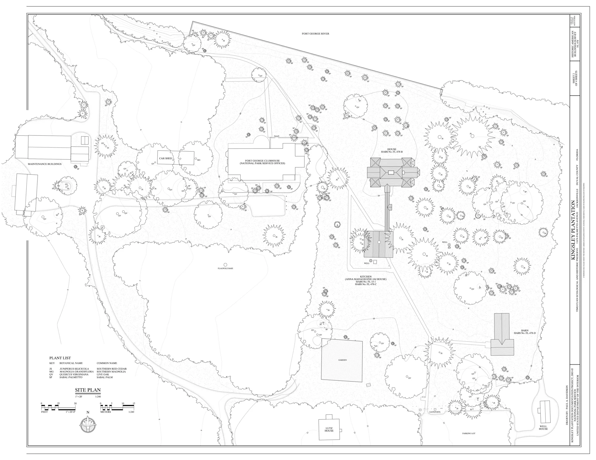
A site plan shows the building in its context: the boundaries of the plot, the building’s footprint, access, parking, landscape, levels and north point. It is usually the first drawing in a set and the one planning authorities look at first.
Floor plans
A floor plan is a horizontal cut through the building, usually about 1.2–1.5 m above the floor, looking down. It shows walls, doors, windows, stairs, fixed furniture and room names, with dimensions. Anything cut by the imaginary plane, such as walls, is drawn with a heavier line, and elements above the cut, like beams or high windows, are dashed. There is one plan for each floor, plus a roof plan.
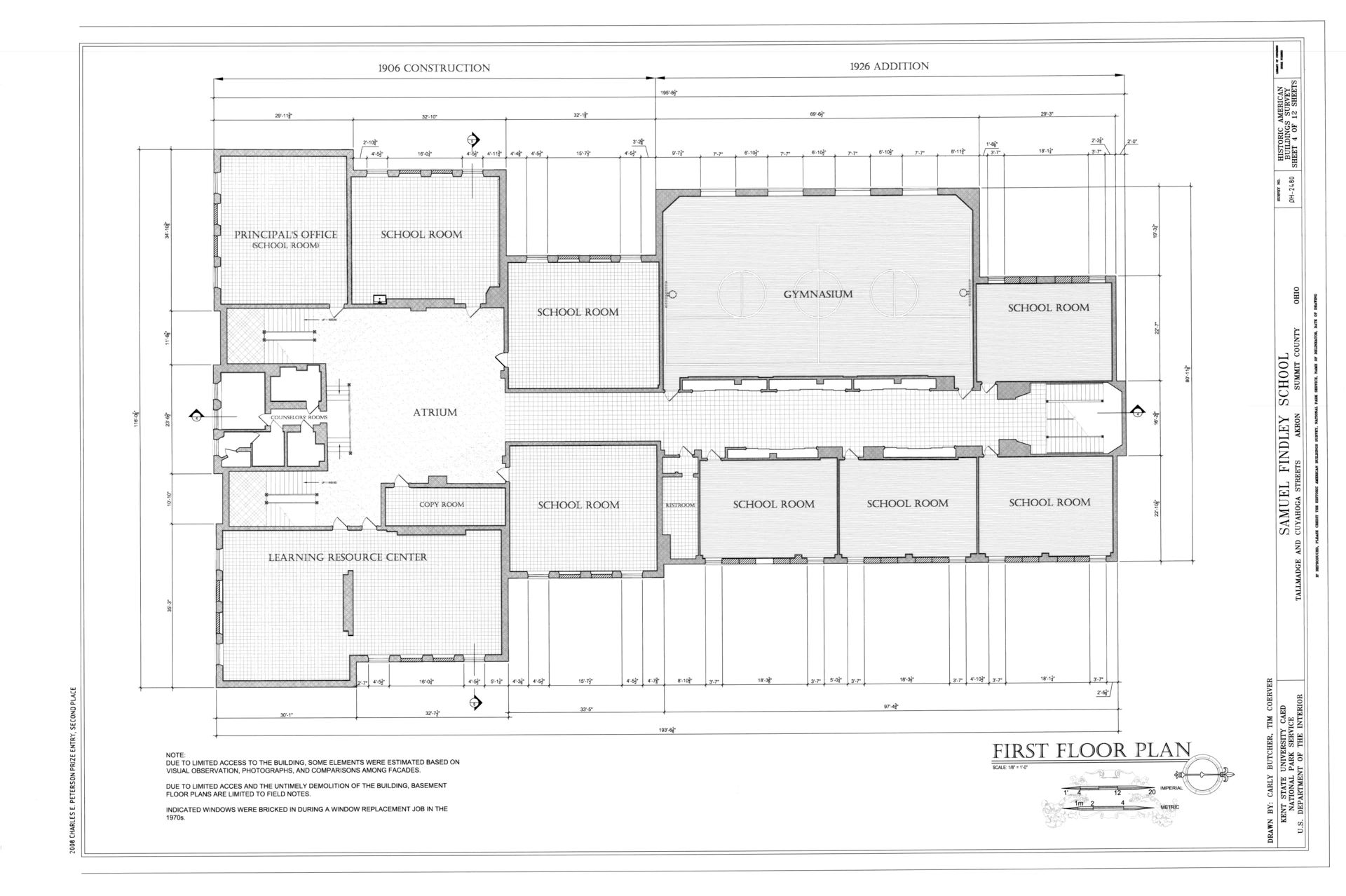
Plans are the drawings most people can read without training, which is why they dominate estate agents’ particulars. But a plan alone cannot show ceiling heights, level changes or how the building stands up, which is why the other drawings are essential.
Sections
A section is a vertical cut through the building, as if it had been sliced and one half removed. It shows floor-to-ceiling heights, the thickness of floors and roofs, stairs, foundations, and how spaces relate vertically, for example a double-height hall. Sections are labelled with letters on the plan (A–A, B–B) to show exactly where the cut is taken.
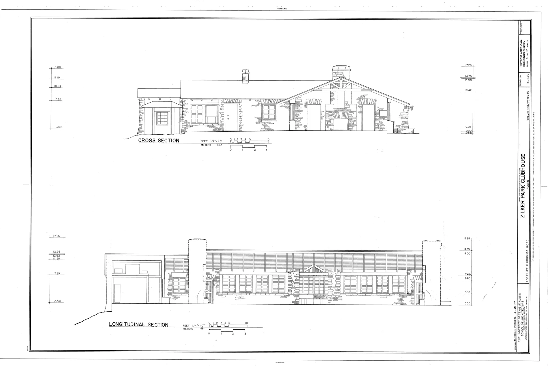
Architects often consider the section the most revealing drawing of all, because it shows the building’s spatial idea and its construction at once. Wall sections, taken at a larger scale through a single wall from foundation to roof, are the bridge between general sections and details.
Elevations
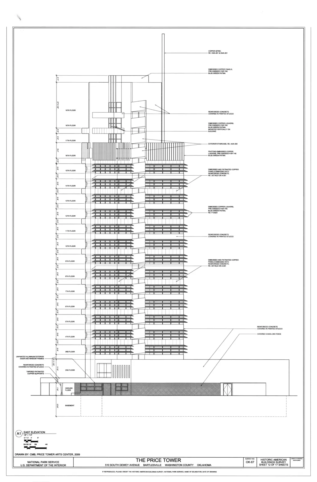
An elevation shows one face of the building as seen straight on, without perspective: the front, rear and side elevations, often named by compass direction (north elevation and so on). Elevations show materials, window and door positions, roof shapes and heights above ground, and are the drawings that best describe the building’s appearance.
Axonometric and perspective views
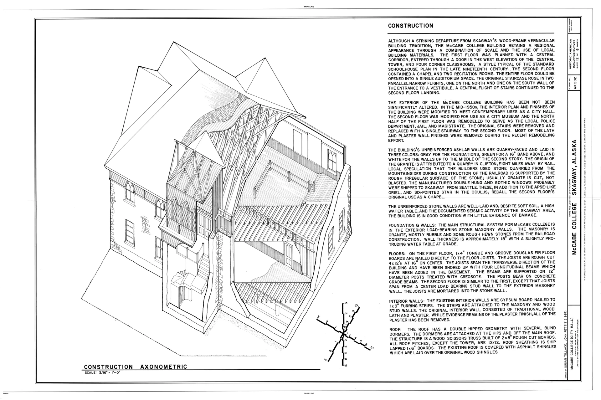
Plans, sections and elevations are precise but abstract. Three-dimensional views help people understand the whole. An axonometric drawing shows the building from above at an angle, with all three dimensions drawn to scale, so it is both measurable and easy to read; exploded axonometrics pull components apart to show how they fit together. A perspective shows the building as the eye sees it, with lines converging towards vanishing points, which makes it the most realistic but not measurable.
Details
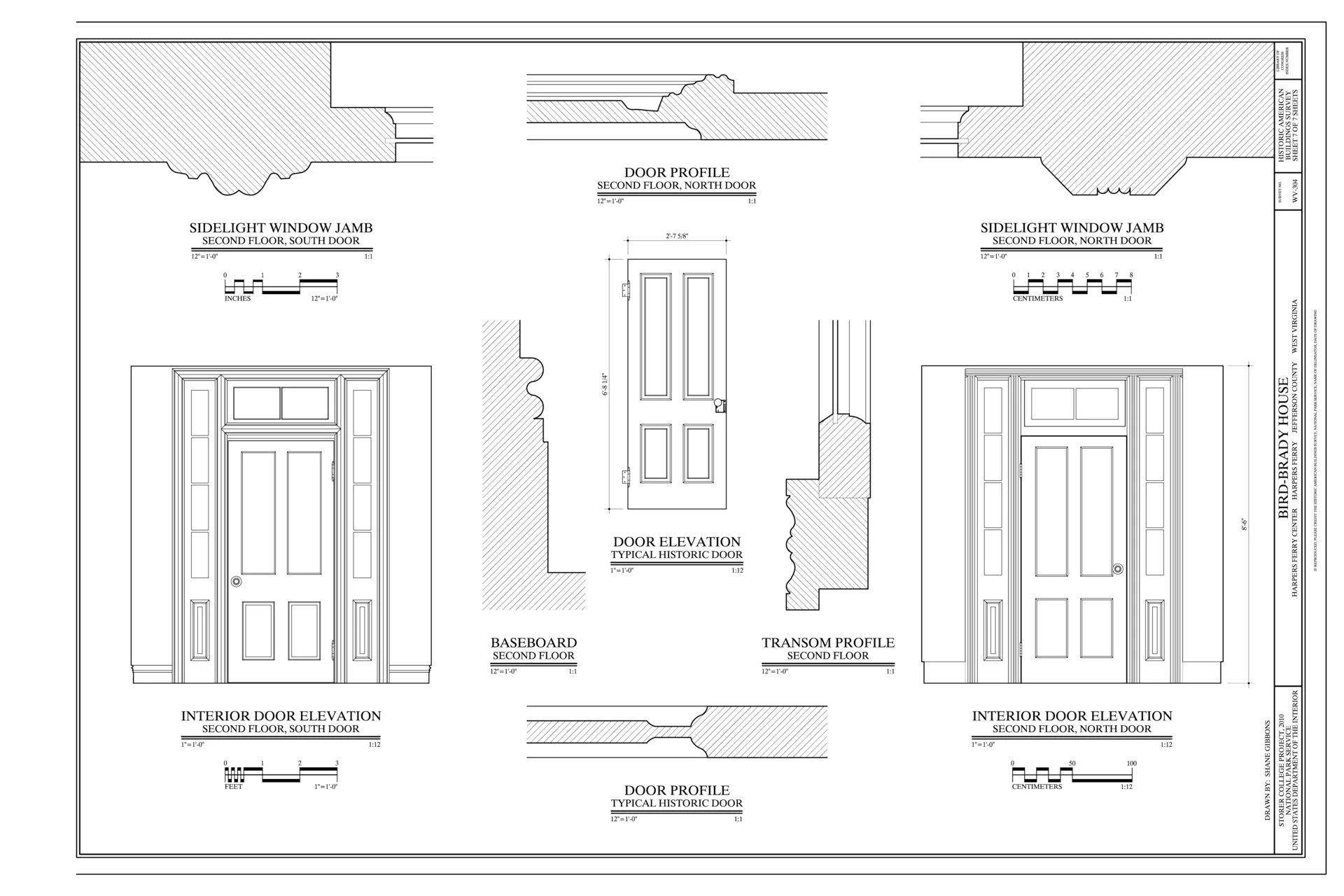
Details are large-scale drawings, typically 1:20 to 1:2, of the places where materials meet: the junction of wall and roof, a window head, a stair nosing, a balustrade fixing. They show every layer, fixing and dimension the builder needs, and they are where most of a building’s quality and weather-tightness is decided. A small house may need dozens of details; a large building, hundreds.
Schedules and specifications
Not everything is best drawn. Schedules are tables that list every door, window, finish or fixture with its type, size and specification, cross-referenced to codes on the plans. Specifications are written documents that describe materials, products and standards of workmanship. Together with the drawings, they make up the contract documents a contractor prices and builds from.
Architectural drawing sets by project stage
The drawing set grows as the project develops. The table shows the typical drawings at each stage.
| Stage | Purpose | Typical drawings | Typical scales |
|---|---|---|---|
| Survey and brief | Record what exists | Measured site plan, existing plans, sections, elevations | 1:500–1:100 |
| Concept design | Test and present ideas | Sketch plans and sections, massing models, perspectives | 1:200–1:100 |
| Developed design / planning | Coordinate and seek approval | Site plan, plans, sections, elevations, key details | 1:500–1:50 |
| Technical design / construction documents | Describe exactly what to build | Full plans, sections, elevations, wall sections, details, schedules, specifications | 1:100–1:2 |
| Construction | Answer questions and record changes | Revised drawings, sketches, shop-drawing reviews | As needed |
| Completion | Record what was built | As-built (record) drawings | 1:100–1:50 |
Source: Arch2O summary of standard practice; scales after ISO 5455 recommended series and common industry practice (as of 21 October 2026).
The same plan, section and elevation are redrawn several times at increasing levels of detail. Today most practices produce them from a single 3D building information model (BIM), so that a change in one view updates all the others; our comparison of architectural design software explains the main tools.
Can I draw my own architectural plans?
Yes, for many purposes: measured sketches of your home, layout studies and simple drawings for a contractor’s quote can be produced by anyone who works carefully to scale. Free and low-cost CAD and home-design programs make it easier. Whether your own drawings can be submitted for planning or building approval depends on your jurisdiction and the project: many places require drawings for larger or more complex projects to be prepared or sealed by a licensed architect or engineer, and almost all require compliance with building codes that self-drawn plans often miss. Check with your local authority before relying on them.
Check whether the drawing set tells one consistent story
Choose one door, stair or external wall and follow it from plan to section, elevation and detail. Its location, level, reference and material should agree wherever it appears. Use a clear revision record so a builder can distinguish current information from a superseded sheet. If a dimension or specification conflicts, identify which document governs and resolve the conflict before issue. A persuasive perspective does not replace a dimensioned plan, and a detailed section does not establish that the entire building has been coordinated.
When presenting the resulting drawing, our architecture presentation board tips can help organise the information clearly.
Summary: reading a set of architectural drawings
- Start with the site plan to understand where the building sits and where north is.
- Read the floor plans for the layout, and find the section markers.
- Read the sections at those markers to understand heights and levels.
- Read the elevations for appearance and materials.
- Use the axonometric or perspective to check your mental picture.
- Go to the details and schedules for how it is built.
Read together in that order, architectural drawings describe a building completely, which is exactly what they are for.

Luca Moretti is a content strategist with a foundation in urban design and architecture. Based in Milan, he focuses on writing that bridges aesthetics, material culture, and everyday spatial experiences.