

Stack ventilation moves air through a building using buoyancy: warm indoor air is lighter than cooler outdoor air, so it rises and leaves through high-level openings while fresh air is drawn in low down. The flow depends on three things the architect controls in section: the height between the inlet and outlet, the size of the openings, and the temperature difference between inside and out. This guide sets out a step-by-step method with one worked example on a clearly hypothetical studio building, using the standard stack-flow equation, and explains the climate limits that decide whether stack ventilation will work at all. It is an early-design method; final sizing needs an engineer and a check against your local regulations.
How stack ventilation works
Air pressure falls with height, and it falls faster in cold, dense air than in warm, light air. When a building is warmer than the outdoors, the pressure inside at the top is slightly higher than outside, and the pressure at the bottom is slightly lower. Air therefore leaks in at low level and out at high level. Somewhere between the two is the neutral pressure level, where the inside and outside pressures match. The taller the stack and the larger the temperature difference, the stronger the flow.
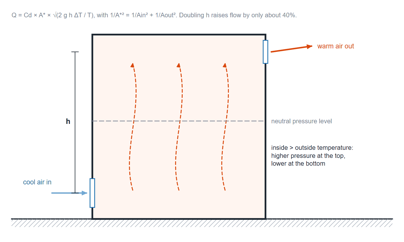
Stack ventilation in section: when the inside is warmer than outside, air enters at low level and leaves at high level, with the neutral pressure level between. Flow rises with the square root of the height h between opening centres and of the temperature difference: Q = Cd × A* × √(2 g h ΔT / T). Diagram: Arch2O
For two openings connected by a vertical path, the volume flow rate is commonly estimated with this equation, used in CIBSE and ASHRAE guidance in slightly different forms:
Q = Cd × A* × √(2 g h ΔT / T)
- Q is the airflow in m³/s.
- Cd is the discharge coefficient of the openings, about 0.6 for a typical sharp-edged window or louvre opening; manufacturers give tested values for their products.
- A* is the combined free area of the openings in m². Inlet and outlet act in series, so 1/A*² = 1/Ain² + 1/Aout². Two equal openings of area A give A* = A/√2.
- g is gravitational acceleration, 9.81 m/s².
- h is the vertical distance between the centres of the inlet and outlet, in m.
- ΔT is the inside-outside temperature difference in K, and T is the mean absolute temperature, in kelvin (°C + 273).
Because airflow rises only with the square root of height and temperature difference, doubling the stack height does not double the flow; it increases it by about 40%. The equation ignores wind, which can help or oppose the stack, so treat the result as the still-air case, which is the usual design condition for summer.
Step-by-step method
- Define the design condition. Choose a summer outdoor temperature from local climate data and the indoor temperature you can accept. The difference, often only 2–5 K on a warm day, is the ΔT that drives the flow.
- Estimate the heat to remove. Add internal gains (people, lighting, equipment) and solar gains that get through shading, in watts. The airflow needed to remove heat W at a temperature rise ΔT is Q = W / (ρ × cp × ΔT), with air density ρ ≈ 1.2 kg/m³ and specific heat cp ≈ 1,005 J/kg·K.
- Draw the section. Place inlets low and outlets as high as possible, and give the air a clear route between them: open plan, transfer grilles, a stair or atrium. Measure h between opening centres.
- Size the openings. Rearrange the equation to find the effective area, then the free areas of the inlet and outlet.
- Check the constraints. Security, rain, noise, insects, fire compartmentation, draughts in winter and controls all affect whether the openings can be used as designed.
Worked example: a double-height studio
Take a hypothetical studio of 200 m² with a 7.5 m high space, low windows along one side and high-level vents in a rooflight upstand. Assume:
- Internal and solar gains of 30 W/m², so W = 200 × 30 = 6,000 W.
- An acceptable temperature rise of 3 K above outdoor air, with the inside at about 25 °C (T ≈ 298 K).
- A height of 7 m between the centres of the low inlets and the high outlets.
- A discharge coefficient Cd of 0.61 and equal inlet and outlet areas.
Step A, airflow needed: Q = 6,000 / (1.2 × 1,005 × 3) = 1.66 m³/s, which is about four air changes an hour for a volume of 1,500 m³.
Step B, driving term: √(2 × 9.81 × 7 × 3 / 298) = √1.38 = 1.18 m/s.
Step C, areas: Cd × A* = 1.66 / 1.18 = 1.41 m², so A* = 1.41 / 0.61 = 2.31 m². With equal openings, each needs A = 2.31 × √2 = 3.27 m² of free area, about 1.6% of the floor area for the inlets and the same again for the outlets.
| Stack height h (m) | Airflow needed (m³/s) | Free area per opening (m²) | Per opening as % of floor area |
|---|---|---|---|
| 3.5 | 1.66 | 4.6 | 2.3% |
| 7.0 | 1.66 | 3.3 | 1.6% |
| 10.5 | 1.66 | 2.7 | 1.3% |
Source: Arch2O calculation using Q = Cd A* sqrt(2 g h dT / T); illustrative only (as of 29 October 2026).
The table shows the section at work. Halving the stack height to 3.5 m, as in a single-storey room with high windows, raises each opening to about 4.6 m². Raising it to 10.5 m with a roof stack reduces it to about 2.7 m². The smaller opening controls the path: doubling the inlet while keeping the outlet the same raises the combined area A* from 0.71 to only 0.89 times the outlet area, about 26% more flow, so it is usually better to enlarge whichever opening is smallest.
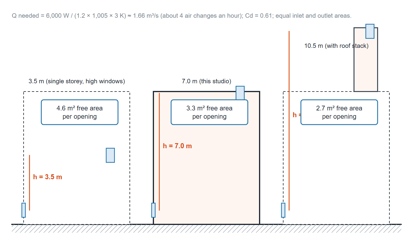
The worked example studio (200 m², 7.5 m high, 6 kW of gains, 3 K rise): it needs about 1.66 m³/s, so with 7 m between inlet and outlet centres each opening needs about 3.3 m² of free area (1.6% of floor area). At 3.5 m that rises to about 4.6 m²; with a 10.5 m roof stack it falls to about 2.7 m². Diagram: Arch2O
Openings and section design
- Inlets: low enough to work with the stack, but not so low that cold incoming air causes draughts at desk height in cooler weather; many designs use high-level inlets in winter and low ones in summer, or temper air through a floor plenum.
- Outlets: as high as possible, sheltered from rain and on a side or roof position where wind suction helps rather than blows back in. Stacks that rise above the roof and terminals with wind cowls make the outlet less sensitive to wind direction.
- Free area, not opening size: louvres, insect mesh and window hinges reduce the free area, sometimes by half. Use the manufacturer’s measured free area and discharge coefficient.
- Air paths: every room on the route needs an outlet path. Atria, stairs and corridors can act as stacks, but they must work with fire strategy and compartmentation, which may require dampers or automatic closing.
- Controls: automatic actuators on high windows, linked to temperature and rain sensors, let the building ventilate at night and close in storms; occupants should still be able to open nearby windows.
Climate constraints
Stack ventilation needs the inside to be warmer than the outside. It works best in temperate climates, in spring and autumn, and at night, when outdoor air is cool. On hot afternoons, when the outdoor temperature approaches or exceeds the acceptable indoor temperature, ΔT shrinks towards zero and the stack stops working; in hot-humid climates, outdoor air may be too humid to provide comfort. Strategies that help include night-time purge ventilation with exposed thermal mass to store coolth, solar chimneys that heat the stack air above room temperature, and mixed-mode systems that switch to mechanical cooling in peak conditions. In cold climates, the stack effect is strong in winter, so openings must be small and controlled to avoid heat loss and draughts. Local noise and air pollution can rule out openable windows on busy streets.
Built precedents
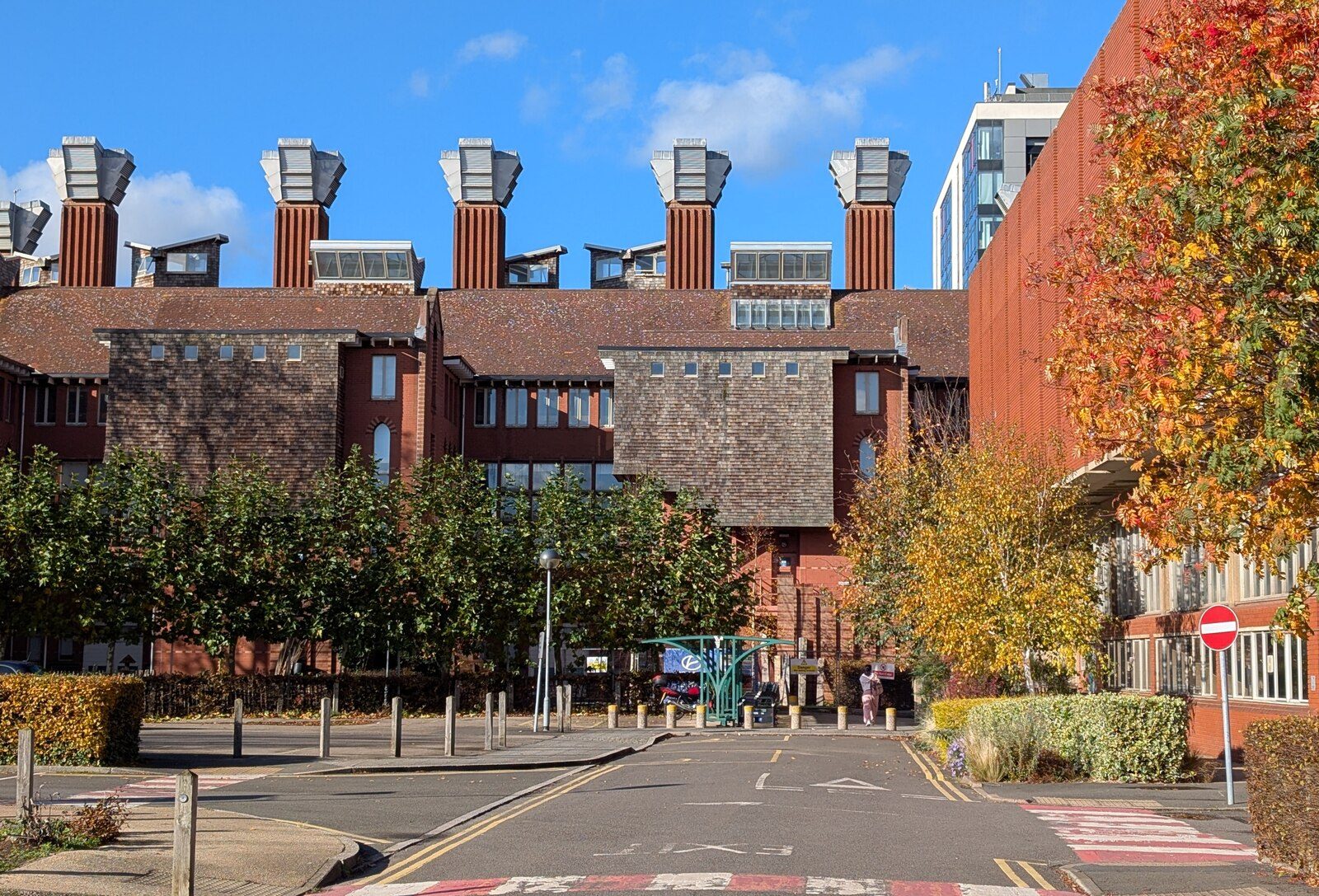
The ventilation stacks of the Queens Building rise above its lecture theatres. Photo: Mat Fascione, CC BY-SA 2.0, via Wikimedia Commons. Mat Fascione, source, CC BY-SA 2.0
The Queens Building at De Montfort University in Leicester, designed by Short Ford Associates with the engineer Max Fordham and completed in 1993, is a benchmark of naturally ventilated design in the UK. Its tall brick stacks draw air through lecture theatres and laboratories, and its ventilation and thermal performance were monitored from 1993 to 1996.
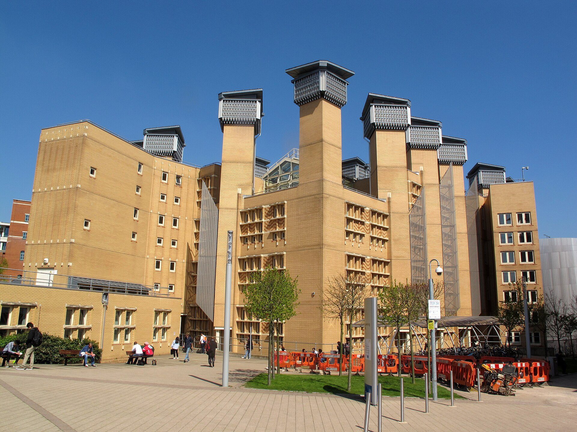
The perimeter stacks of the Lanchester Library, Coventry University (2000). Photo: Keith Williams, CC BY-SA 2.0, via Wikimedia Commons. Keith Williams, source, CC BY-SA 2.0
The Lanchester Library at Coventry University, opened in 2000 and also designed by Short and Associates, takes the idea to a deep-plan building. Fresh air is supplied from a plenum below the ground floor into four lightwells, flows across the floors and is drawn out through a central lightwell and perimeter stacks, as described in the design paper by Cook, Lomas and Eppel (CIBSE National Conference, 1999); a later monitoring study examined how it performed in use.
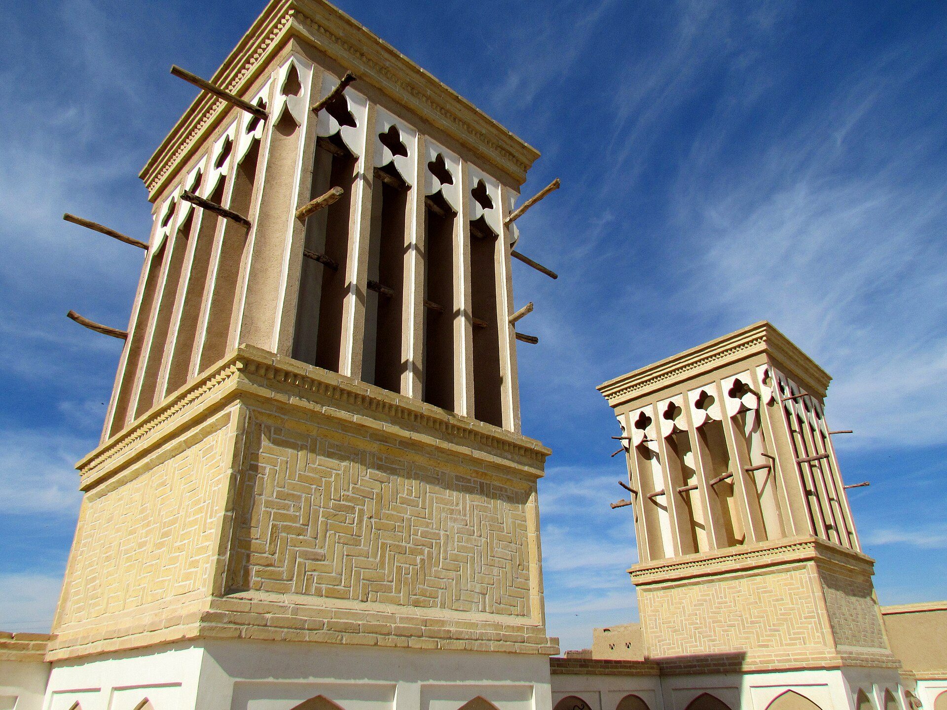
Windcatchers (badgirs) in Yazd, Iran. Photo: Alireza Javaheri, CC BY 3.0, via Wikimedia Commons. Alireza Javaheri, source, CC BY 3.0
Traditional buildings used related principles long before the equation: the windcatchers of Yazd in Iran catch wind at high level and, when the air is still, can work as stacks, exhausting warm air from the rooms below. Stack ventilation is one of several passive strategies in sustainable architecture; it is most effective combined with shading, thermal mass and careful planning of the section.
Checklist before you finalise the design
- Design ΔT from local climate data, with a plan for the hottest days.
- Heat gains estimated and reduced first with shading and efficient equipment.
- Stack height measured between opening centres in the final section.
- Free areas and discharge coefficients from product data, not nominal sizes.
- Smallest opening on the air path identified and enlarged if it throttles the flow.
- Fire, security, rain, noise and insect protection resolved for every opening.
- Controls and night ventilation agreed with the building’s users and engineer.
Sources and further reading
- CIBSE, basic concepts for natural ventilation of buildings (H. Awbi, University of Reading); the full method is in CIBSE AM10, Natural ventilation in non-domestic buildings.
- CIBSE Journal, guidance on ventilation openings (effective area and discharge coefficient).
- Cook, Lomas and Eppel, design and operating concept for an innovative naturally ventilated library (CIBSE National Conference 1999, via AIVC).
- Loughborough University, performance monitoring of a naturally ventilated city-centre library (PLEA 2006).

Luca Moretti is a content strategist with a foundation in urban design and architecture. Based in Milan, he focuses on writing that bridges aesthetics, material culture, and everyday spatial experiences.